Mastering Machine Simulation in PowerMill Ultimate: A Comprehensive Guide for CNC Machinists
Introduction:
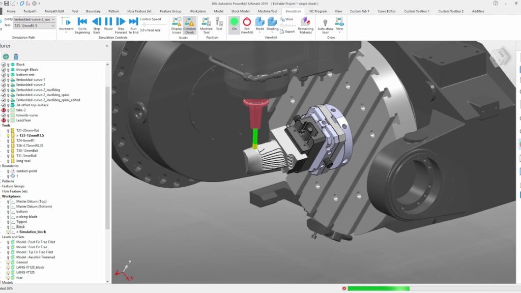
Machine simulation is a critical component of CNC (Computer Numerical Control) machining that allows machinists to visualize, verify, and optimize machining processes before execution on the CNC machine. PowerMill Ultimate, developed by Autodesk, is a leading CAM (Computer-Aided Manufacturing) software solution that offers robust capabilities for machine simulation, enabling machinists to simulate machine tool movements, toolpaths, material removal, and collision detection in a virtual environment. Understanding how to use machine simulation effectively in PowerMill Ultimate is essential for reducing errors, minimizing scrap, and maximizing productivity in CNC machining operations. In this comprehensive guide, we will delve into the intricacies of machine simulation in PowerMill Ultimate, covering essential concepts, workflow, best practices, and advanced techniques. Whether you’re a novice CNC machinist or an experienced professional seeking to enhance your simulation skills, this guide will equip you with the knowledge and skills necessary to master machine simulation effectively in PowerMill Ultimate.
Understanding Machine Simulation in PowerMill Ultimate:
Machine simulation in PowerMill Ultimate refers to the process of visualizing and analyzing machining operations in a virtual environment to simulate machine tool movements, toolpaths, material removal, and collision detection. PowerMill Ultimate offers advanced simulation capabilities that allow machinists to simulate various types of CNC machines, including milling machines, turning centers, wire EDM (Electrical Discharge Machining) machines, and multi-axis machining centers. By simulating machining processes in PowerMill Ultimate, machinists can identify potential issues, optimize toolpaths, and validate machining programs before execution on the CNC machine, thereby minimizing risks and ensuring machining accuracy.
Navigating the PowerMill Ultimate Interface:
Before using machine simulation in PowerMill Ultimate, familiarize yourself with the software interface and navigation tools. The PowerMill Ultimate interface consists of various menus, toolbars, panels, and viewport windows that provide access to different functionalities and features. Understand the purpose and function of each interface element, such as the Ribbon Bar for accessing commands, the Browser for organizing project data, the Graphics Window for visualizing toolpaths, and the Simulation Panel for configuring simulation settings. Practice navigating the interface and performing basic tasks to become comfortable with the simulation environment.
Importing CAD Models and Toolpaths:
To perform machine simulation in PowerMill Ultimate, import CAD (Computer-Aided Design) models of the workpiece and toolpaths generated by the CAM software. PowerMill Ultimate supports various CAD file formats, including STEP, IGES, SAT, and STL, allowing machinists to import 3D models of the workpiece, fixtures, and machine components. Additionally, import toolpaths generated by PowerMill Ultimate or other CAM software packages to visualize machining operations and simulate material removal. Organize imported CAD models and toolpaths into separate groups or layers for better visualization and analysis during simulation.
Configuring Machine Parameters and Setup:
Once CAD models and toolpaths are imported, configure machine parameters and setup options in PowerMill Ultimate to define the virtual machining environment for simulation. Specify machine properties such as machine type, axis configuration, work envelope, spindle speed, feed rate, and tooling specifications to match the characteristics of the actual CNC machine. Define workpiece setup parameters such as workpiece orientation, clamping positions, and fixture locations to simulate realistic workpiece setups and machining scenarios. Verify machine setup options and adjust parameters as needed to accurately represent the machining process.
Setting Simulation Preferences and Options:
Configure simulation preferences and options in PowerMill Ultimate to customize simulation behaviors, visualization settings, and analysis tools according to your preferences and requirements. Access the Simulation Preferences dialog box to define parameters such as simulation speed, playback controls, animation settings, and display options for toolpaths, tooling, and material removal. Enable collision detection features to identify potential collisions between cutting tools, workpiece surfaces, fixtures, and machine components during simulation. Adjust simulation resolution, accuracy, and performance settings to balance realism with computational efficiency.
Performing Machine Simulation and Analysis:
With CAD models, toolpaths, and simulation settings configured, perform machine simulation in PowerMill Ultimate to visualize machining operations and analyze simulation results. Use the Simulation command to initiate simulation playback and observe machine tool movements, toolpaths, material removal, and chip formation in real-time. Analyze simulation results for issues such as tool collisions, interference, toolpath errors, excessive material removal, or machining inaccuracies. Utilize simulation analysis tools such as section views, measurement tools, and collision reports to identify and resolve issues during simulation.
Optimizing Toolpaths and Machining Parameters:
During machine simulation in PowerMill Ultimate, optimize toolpaths and machining parameters based on simulation feedback and analysis results. Adjust cutting parameters such as spindle speed, feed rate, depth of cut, and stepover value to optimize material removal rates and machining efficiency. Modify toolpath strategies such as toolpath orientation, toolpath pattern, and tool engagement angle to minimize tool wear, reduce cutting forces, and improve surface finish quality. Experiment with different machining parameters and toolpath techniques to optimize machining performance and achieve desired machining outcomes.
Validating Machining Programs and G-Code Output:
After performing machine simulation and optimizing toolpaths, validate machining programs and G-code output in PowerMill Ultimate to ensure compatibility with the CNC machine and verify machining accuracy. Use the Post Process command to generate machine-specific G-code output for the CNC machine based on the optimized toolpaths. Review the generated G-code output to verify tool change commands, spindle commands, feed commands, and other machine-specific codes. Simulate the G-code output in PowerMill Ultimate to validate machining programs, detect errors, and ensure consistency between simulation results and actual machining performance.
Documenting and Reviewing Simulation Results:
Document simulation results and review them regularly to capture lessons learned, best practices, and insights gained from machine simulation in PowerMill Ultimate. Create simulation reports detailing simulation parameters, analysis results, optimization strategies, and recommendations for future machining operations. Document issues encountered during simulation, along with their resolutions and impact on machining performance. Review simulation results with colleagues, supervisors, or customers to facilitate knowledge sharing, collaboration, and decision-making in CNC machining projects. Incorporate feedback from simulation reviews into future machining processes to improve efficiency and quality.
Implementing Best Practices and Safety Measures:
To ensure effective and safe machine simulation in PowerMill Ultimate, implement best practices and safety measures throughout the simulation process. Some recommended practices include:
Regularly update CAD models, toolpaths, and simulation parameters to reflect changes in machining requirements, part designs, or tooling specifications.
Perform thorough simulation checks and analysis before executing machining programs on the CNC machine to minimize risks and prevent errors.
Collaborate with colleagues, tooling suppliers, and CNC machine operators to validate simulation results, address issues, and optimize machining processes.
Adhere to industry regulations, safety standards, and best practices for machine simulation, including collision detection, clearance checking, and material removal simulation.
Conduct periodic training and refresher courses for operators and machinists on machine simulation techniques, software features, and simulation best practices.
Conclusion:
Machine simulation in PowerMill Ultimate is a powerful tool that enables CNC machinists to visualize, verify, and optimize machining processes in a virtual environment. By understanding the principles of machine simulation, importing CAD models and toolpaths, configuring machine parameters and setup, setting simulation preferences and options, performing simulation and analysis, optimizing toolpaths and machining parameters, validating machining programs and G-code output, documenting simulation results, and implementing best practices and safety measures, machinists can master the art of machine simulation effectively in PowerMill Ultimate. With the knowledge and skills acquired from this guide, machinists can streamline their simulation workflows, improve machining efficiency, and achieve exceptional results in CNC machining applications.